
What the Mux? Adding analog inputs to Daisy!
Takumi OgataDaisy Seed comes with 12 ADC pins for connecting components like potentiometers.
But what if you need more inputs??
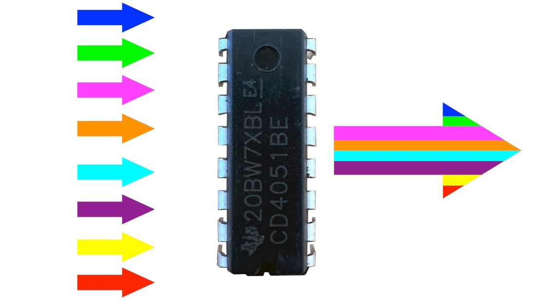
CD4051 multiplexer is what you need!
What Is a Multiplexer? 📖
Multiplexer (AKA mux) is an electronics component that has multiple inputs with a single output, and each of these inputs are individually sent out at a different time. It is commonly used to expand the number of available inputs on a microcontroller.
Microcontrollers have several ADCs (analog-to-digital converters) and you generally connect 1 component, like a potentiometer knob, to one of the ADCs (for controlling a synth volume as an example). With the multiplexer, like the CD4051 which has 8-channels of input, you can connect up to 8 potentiometers to its inputs and have the single output read by one of the ADCs on a microcontroller. This means that you can have up to 8 inputs per 1 onboard ADC with the power of a multiplexer!
While there are 12 ADCs on the Daisy, you may think of various applications where you need more analog inputs.
Let’s say you want to build a hardware drum machine with snare, kick, hi-hat, and crash with ADSR parameters (4 individual parameters) that’s controlled by a potentiometer separately for each of the 4 voices. For this project, you would need at least 16 ADCs (4x4), which exceeds the number of available ADCs on the Daisy. To address this, you can use 1 multiplexer and have a total of 19 inputs available!
You may be curious to know if it’s possible to have a multiplexer for each of the 12 ADCs to have 96 total inputs. You can actually do that if you want! But, the direct connection to the single ADC pin will read 8 times faster than the overall multiplexer bus bandwidth when mixing and matching individual channels and multiplexers. So the key strategy here is to use the individual ADC for getting faster reads for important controls while loading up on multiplexers for controls where input rate doesn't matter as much.
Using a Multiplexer with Daisy! 🤔
We will be using the CD4051 multiplexer for this tutorial, which has 8-channel of inputs, and it is also recommended to have the below items to complete the tutorial.
- Daisy Seed x1 [Electrosmith]
- Micro USB Cable x1 [Electrosmith]
- Full Sized Breadboard x1 [Adafruit]
- Jumper Wires x1 [Adafruit] [Amazon]
- Potentiometer x4 (or up to x8) [Thonk UK]
- Multiplexer x1 [Mouser]
If you are using Pure Data and/or Oopsy:
- 3.5mm Jack x1 [Adafruit] [Thonk UK]
- 3.5mm TS Cable x1 [Perfect Circuit]
Download the tutorial Fritzing file.
Download the tutorial KiCAD file.

CD4051
There are a lot of pins on the CD4051 and they’re not labeled like in a typical breakout board.
So, let’s have a look at a diagram like this.

CD4051B diagram, from the TI CD4051 datasheet
Let’s have a look at pin 3 in the diagram that is labeled “COM OUT/IN”. For your purpose of expanding the ADC, that’s the pin that you’ll connect to the Daisy’s ADC.
So, let’s connect the CD4051 pin 3 (COM OUT/IN) to the Daisy pin D15 (ADC 0)!


Next, let’s look at the “CHANNELS IN/OUT” pins with a number next to each. You can think of these as the “expanded ADCs”.

For example, you can connect a potentiometer’s analog out pin to multiplexer’s pin 13, which you can think of as input 0 as indicated by the number “0” next to it. For the 2nd potentiometer, you can connect it to pin 14, which you can think of as input 1. And so on up to 8 total inputs!
For this tutorial, you’ll connect 4 potentiometers.


But, if you have data from 4 potentiometers sent into a single ADC all at once like this, that’s not gonna end pretty, right? Enter Selector Pins!!
Selector Pins👆
Pins 11, 10, and 9 on the multiplexer are called selector pins.
For CD4051, these pins are labeled as A, B, and C on diagrams and schematics. You may see the symbols S0, S1, and S2 used for the selector pins, and we’ll use that for this tutorial as we think that it makes explaining the multiplexers a bit easier.

These pins will help give order to the multiple inputs (maximum of 8 sensor data) coming into a single stream towards the Daisy’s ADC. This is achieved by sending digital outs, 0 (LOW) or 1 (HIGH), from the Daisy to these selector pins!!
Any pin with the label ‘D’ (also known as GPIO pin) can be used for digital output, so let’s connect the Daisy’s pin D0 to the multiplexer's pin 11 (S0). Then, the Daisy’s pin D1 to multiplexer’s pin 10 (S1). And the Daisy’s pin D2 to multiplexer’s pin 9 (S2).


Finally, connect 3.3 volts to the multiplexer’s VDD input (pin 16) and then ground pins 6, 7, and 8 as follows.


And done!! You finished hooking up the Daisy to the multiplexer! Ok, let’s learn what these select pins are doing.
Let’s think of doors🚪
Each multiplexer input has 3 different combinations of “doors” or “gates”. And a door opens when a matching “key” is sent from the Daisy’s digital pins.

Blue door opens for digital out LOW (0) and red door opens for digital out HIGH (1). The first potentiometer on the leftmost side is connected to input 0 of the multiplexer. And the next potentiometer to the right is connected to input 1 of the multiplexer and so on…
Let’s take a look at an example.
For S0 = LOW, S1 = LOW, and S2 = LOW, all 3 doors for input 0 will open. For all the other inputs, at least one door is closed, so the data cannot go through; it is gated off!

For S0 = HIGH, S1 = LOW, and S2 = LOW, all 3 doors for input 1 will be opened.

And so on…


Code (Arduino IDE)⌨️
Here’s the code for up to 8 inputs.
    #include "DaisyDuino.h"

#define analogPin0 A0 //ADC 0
#define pinS2 2 //Pin D2
#define pinS1 1 //Pin D1
#define pinS0 0 //Pin D0

void setup()
{
  Serial.begin(9600);

  //Set pins D0, D1, and D2 as digital outs
  pinMode(pinS2, OUTPUT);
  pinMode(pinS1, OUTPUT);
  pinMode(pinS0, OUTPUT);
}

void loop()
{

  //Only reading input 0 of the multiplexer
  digitalWrite(pinS2, LOW);
  digitalWrite(pinS1, LOW);
  digitalWrite(pinS0, LOW);
  Serial.print(analogRead(analogPin0));
  Serial.print("  ");

  //Only reading input 1 of the multiplexer
  digitalWrite(pinS2, LOW);
  digitalWrite(pinS1, LOW);
  digitalWrite(pinS0, HIGH);
  Serial.print(analogRead(analogPin0));
  Serial.print("  ");

  //Only reading input 2 of the multiplexer
  digitalWrite(pinS2, LOW);
  digitalWrite(pinS1, HIGH);
  digitalWrite(pinS0, LOW);
  Serial.print(analogRead(analogPin0));
  Serial.print("  ");

  //Only reading input 3 of the multiplexer
  digitalWrite(pinS2, LOW);
  digitalWrite(pinS1, HIGH);
  digitalWrite(pinS0, HIGH);
  Serial.print(analogRead(analogPin0));
  Serial.print("  ");

  //Only reading input 4 of the multiplexer
  digitalWrite(pinS2, HIGH);
  digitalWrite(pinS1, LOW);
  digitalWrite(pinS0, LOW);
  Serial.print(analogRead(analogPin0));
  Serial.print("  ");

  //Only reading input 5 of the multiplexer
  digitalWrite(pinS2, HIGH);
  digitalWrite(pinS1, LOW);
  digitalWrite(pinS0, HIGH);
  Serial.print(analogRead(analogPin0));
  Serial.print("  ");

  //Only reading input 6 of the multiplexer
  digitalWrite(pinS2, HIGH);
  digitalWrite(pinS1, HIGH);
  digitalWrite(pinS0, LOW);
  Serial.print(analogRead(analogPin0));
  Serial.print("  ");

  //Only reading input 7 of the multiplexer
  digitalWrite(pinS2, HIGH);
  digitalWrite(pinS1, HIGH);
  digitalWrite(pinS0, HIGH);
  Serial.println(analogRead(analogPin0));

  delay(50);

}
You can set pins D0, D1, and D3 as digital outs by using the `pinMode()` function like this.
//Set pins D0, D1, and D2 as digital outs

pinMode(pinS2, OUTPUT);

pinMode(pinS1, OUTPUT);

pinMode(pinS0, OUTPUT);
When all three digital pins are set to “LOW”, the `analogRead()` will exclusively be reading the data from multiplexer’s input 0. The data is then displayed using Serial.print().
//Only reading input 0 of the multiplexer

digitalWrite(pinS2, LOW);

digitalWrite(pinS1, LOW);

digitalWrite(pinS0, LOW);

Serial.print(analogRead(analogPin0));

Serial.print(" ");
Here’s only input 0 of the multiplexer being displayed on Arduino IDE’s Serial Monitor. The first knob on the left is connected to input 0 of the multiplexer, the knob next to it on the right is connected to input 1, and so on…

For the combination S2 = LOW, S1 = LOW, and S0 = HIGH, only the multiplexer’s input 1 is read.
//Only reading input 1 of the multiplexer

digitalWrite(pinS2, LOW); digitalWrite(pinS1, LOW);

digitalWrite(pinS0, HIGH);

Serial.print(analogRead(analogPin0));

Serial.print(" ");

This time, twisting the first knob does not affect the displayed output.
Ok, I believe you get the idea for analyzing the rest of the code! Let’s use 4 knobs all at once! Again, keep in mind that only 1 ADC is being used right now!!

The multiple multiplexer inputs are being read one after the other almost simultaneously, which
results in this expansion of ADC inputs!
Code (C++)⌨️
There is a multiplexer function in libDaisy that you can use in C++. Here’s a code that utilizes it!
/** Example of using a CD4051 multiplexor to expand the ADC inputs */
#include "daisy_seed.h"

/** This prevents us from having to type "daisy::" in front of a lot of things. */
using namespace daisy;

/** Global Hardware access */
DaisySeed hw;

int main(void)
{
    /** Initialize our hardware */
    hw.Init();

    /** Configure the ADC
     *
     *  One channel configured for 8 inputs via CD4051 mux.
     *
     */
    AdcChannelConfig adc_cfg;
    adc_cfg.InitMux(seed::A0, 8, seed::D0, seed::D1, seed::D2);

    /** Initialize the ADC with our configuration */
    hw.adc.Init(&adc_cfg, 1);

    /** Start the ADC conversions in the background */
    hw.adc.Start();

    /** Startup the USB Serial port */
    hw.StartLog();

    /** Infinite Loop */
    while(1)
    {
        /** Print the values via Serial every 250ms
         *  Values will be 0 when inputs are 0V
         *  Values will be 65536 when inputs are 3v3
         */
        System::Delay(250);

        hw.Print("Input 1: %d", hw.adc.GetMux(0, 0));
        hw.Print("  ");

        hw.Print("Input 2: %d", hw.adc.GetMux(0, 1));
        hw.Print("  ");

        hw.Print("Input 3: %d", hw.adc.GetMux(0, 2));
        hw.Print("  ");

        hw.Print("Input 4: %d", hw.adc.GetMux(0, 3));
        hw.Print("  ");

        hw.Print("Input 5: %d", hw.adc.GetMux(0, 4));
        hw.Print("  ");

        hw.Print("Input 6: %d", hw.adc.GetMux(0, 5));
        hw.Print("  ");

        hw.Print("Input 7: %d", hw.adc.GetMux(0, 6));
        hw.Print("  ");

        hw.PrintLine("Input 8: %d", hw.adc.GetMux(0, 7));
    }
}
You initialize using:
adc_cfg.InitMux(seed::A0, 8, seed::D0, seed::D1, seed::D2);
First argument is Daisy’s ADC pin. Second argument is how many multiplexer inputs you’re using (note: if you put 4, you may need to ground the third select pin). Rest of the arguments are for the Daisy’s digital out pins (if you put 4 for the 2nd argument, you only need to put two pins).
Then, you can use the GetMux() function to read one multiplexer input at a time. The second argument corresponds to the multiplexer input pins. As an example, hw.Print("Input 1: %d", hw.adc.GetMux(0, 0)); will output the value of the potentiometer that’s connected to input 0.
Let’s see if this works! Here’s what the serial monitor should look like. I’m using Arduino IDE’s Serial Monitor and only printing out 4 potentiometer data at once.

Patch (Pure Data and Oopsy)⌨️
Here’s a zip folder that contains both an example patch and json file.
The patch looks straightforward! You can use this same patch when you’re using 4 separate ADCs or a single multiplexer.


You are going to test by hearing the multiplexer in action. If everything is wired up and configured correctly, you should be able to individually control a sine oscillator’s pitch and amplitude as well as sawtooth’s pitch and amplitude with just a single ADC!
The json file is where you configure the multiplexer.
In ”parents”,"pot_mux": {
"component": "CD4051",
"mux_count": 8,
"pin": { "adc": 15, "sel0": 0, "sel1": 1, "sel2": 2 }
You set the name of the multiplexer component, total number of input, and pin numbers for the Daisy’s ADC and multiplexer’s selector.
In ”components”,"knob1": { "component": "CD4051AnalogControl", "index": 0, "parent": "pot_mux"},
"knob2": { "component": "CD4051AnalogControl", "index": 1, "parent": "pot_mux" },
"knob3": { "component": "CD4051AnalogControl", "index": 2, "parent": "pot_mux" },
"knob4": { "component": "CD4051AnalogControl", "index": 3, "parent": "pot_mux" },
…and so on.
The ”index” value is what allows us to distinguish which potentiometer is connected to which of the multiplexer’s CHANNELS IN pins.
For example, the potentiometer that’s connected to the multiplexer's pin 13 is “index”: 0 and is called “knob1”. Potentiometer that’s connected to pin 14 is ”index”: 1 and is called ”knob2”. And so on!
After flashing the patch with the mux.json file, you can individually control oscillator 1’s pitch with potentiometer 1, oscillator 1’s amplitude with potentiometer 2, oscillator 2’s pitch with potentiometer 3, and oscillator 2’s amplitude with potentiometer 4.
Summary👋
Whenever you need to expand the numbers of ADCs available for a project, then the multiplexer is the way to go!
We hope that this tutorial has provided you with an idea of how the multiplexer works, how to wire it up, and how to program for it.
Happy building!!
Recommended Reading/Watching 📖